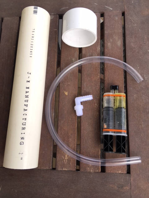
The bell portion of the syphon system is fairly easy to construct. It consists of only a few parts that most people will likely have on hand. It basically consists of a 12″ piece of 2″ PVC pipe, a 2″ pie cap, a 90° 3/8 1/4 barbed nylon nipple and about 14″ I.D. clear tubing. You’ll need some PVC pipe glue and some epoxy or other waterproof glue.
The height of the bell and air break piping must be able to sit within your bucket with the lid on. It is recommended that at least 2″ of clearance remain below the lid of your bucket. You will know if you have it right once the standpipe inside the bucket is inserted.
NOTE: In operation, the water level may pass above the bell before the siphon initiates a dump. If this happens, you will be adjusting the height of the standpipe inside the bell. The bell height does not necessarily need to be adjusted, but can be to put the air break closer to the standpipe.
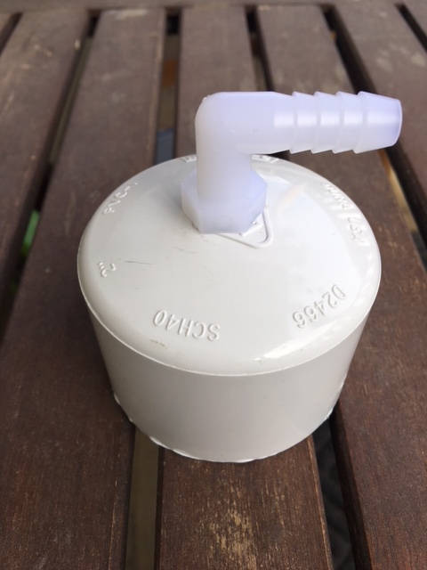
We will be making some additional modifications to the bell so set the 2″ PVC aside for a bit. Take the 2″ cap and drill a 1/2 inch hole into the top right at the center. It is probably best to start from the inside of the cap using a pilot hole. This hole should be slightly smaller than the 90° nipple threads. If you are unsure, its better to drill using smaller bits working your way up to 1/2. What you are looking for is a hole that you can thread before inserting the nipple. If all gos well, you can use a small file or the 1/2 drill itself to widen the hole just enough that the nipple starts to thread in by itself.
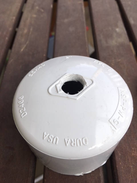
At this point, you should be able to thread the nipple in without having to use any tools to cut threads in the cap. Once you can fully screw that in, glue it in place with epoxy or any waterproof glue. The stronger the glue, the better because you will be pushing tubing on the barbed end later. You don’t want it to pop out or leak air when you shove the tubing on it.
At this point we are going to ct the bottom of the 2″ PVC and create the opening that water can come into the bell siphon. What we are actually looking to do is create an opening sufficient enough to not impede the maximum dump volume of the siphon but also to create a swirl in the water as it enters the bell. Getting the water to spiral in during the dump will aid in breaking the siphon when the cycle is complete. When the air break tube draws air into the top of the siphon, the centripetal force of the water will tend to fling it towards the outside of the bell while the lighter air entering will be funneled towards the center and standpipe making a fast, clean break of the siphon. The slots we will cut on the bottom of the 2″PVC and subsequent heat shaping of the plastic will create the opening we need and the swirling effect we also desire.
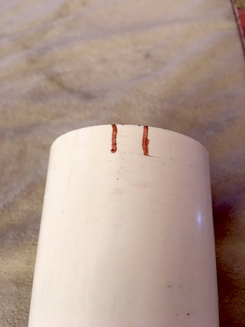
We start by indexing the pipe with 4, 1/4 inch markings where we will make our cuts. At these points, we will make one, L shaped cut from the left index at each quadrant back to the right ending at the right marking at the previous quadrant. You can use a jig saw (run at slow speed or all you will do is melt pipe on the blade trying to make that tight radius) or a coping saw. Us whatever will give you a clean cut. Make the 4 L shaped cuts and then we will heat shape the plastic.